Call Us: 858-784-0900
Email Us: Sales@ACETEC.com

News

Mark Hoffman No Comments

pSemi Introduces Family of Switch + LNA Modules for 5G Massive MIMO Base Stations

Ideal for Sub-6 GHz Remote Radio Units, the Front-end Modules Deliver an Ultra-low Noise Figure and Low Power Consumption 

PHILADELPHIA – INTERNATIONAL MICROWAVE SYMPOSIUM (IMS) – June 12, 2018 – In IMS Booth #1349, pSemiTM Corporation (formerly known as Peregrine Semiconductor), a Murata company focused on semiconductor integration, introduces a family of switch + low-noise amplifier (LNA) modules for 5G massive multiple-input, multiple-output (MIMO) base stations. With an ultra-low noise figure and excellent input power handling, these modules are ideal for protecting remote radio units that operate in the sub-6 GHz frequency bands.

“As massive MIMO increases the number of transmit and receive channels, base-station equipment manufacturers are requiring more highly-integrated and low-power solutions,” says Jim Cable, chief technology officer of pSemi, a Murata company. “Building on our 30-year history of RF integration, pSemi combines our high-performance switch and LNA products into a family of integrated front-end modules. Compared to competing solutions, the pSemi switch + LNA modules have lower power consumption and superior ESD robustness. But most importantly, the overall solution size is 60 percent smaller due to integration and the fact that no external RF matching components are required.”

The switch + LNA modules—the PE53111, PE53211, PE53110 and PE53210—support sub-6 GHz 5G new radio (NR) bands and meet the stringent RF system requirements of massive MIMO base stations. The PE53111 and the PE53211 cover a frequency range from 2.3 to 2.7 GHz (bands 40, 41, n7, n38, n41), while the PE53110 and PE53210 extend from 3.3 to 3.8 GHz (bands 42, 43, n78). In a single-channel or dual-channel configuration, the receiver modules integrate two-channel LNAs with bypass function and high-power switches. An on-chip, fail-safe switch—with over 5W average power handling—improves the overall robustness of the receive channels. Design engineers can control each channel individually within the selected frequency band, offering flexibility in the overall system design. Regarding performance, the pSemi switch + LNA modules deliver a very low noise figure, high linearity and low power consumption. The modules offer ESD protection up to 1kV HBM and operate in environments up to 105 degrees Celsius.

Offered in a 32-lead, 5 x 5 mm LGA package, the PE53111, PE53211, PE53110 and PE53210 are now available as engineering samples. Contact sales@psemi.com to request samples.

Visit pSemi at IMS booth #1349 to see the switch + LNA modules on display.

About pSemi

pSemi Corporation is a Murata company driving semiconductor integration. pSemi builds on Peregrine Semiconductor’s 30-year legacy of technology advancements and strong IP portfolio but with a new mission: to enhance Murata’s world-class capabilities with high-performance RF, analog, mixed-signal and optical solutions. With a strong foundation in RF integration, pSemi’s product portfolio now spans power management, connected sensors, optical transceivers antenna tuning and RF frontends. These intelligent and efficient semiconductors enable advanced modules for smartphones, base stations, personal computers, electric vehicles, data centers, IoT devices and healthcare. From headquarters in San Diego and offices around the world, pSemi’s team explores new ways to make electronics for the connected world smaller, thinner, faster and better. To view pSemi’s semiconductor advancements or to join the pSemi team, visit www.psemi.com.

###

The Peregrine Semiconductor name, Peregrine Semiconductor logo and UltraCMOS are registered trademarks and the pSemi name, pSemi logo, HaRP and DuNE are trademarks of pSemi Corporation in the U.S. and other countries. All other trademarks are the property of their respective companies. The pSemi website is copyrighted by pSemi Corporation. All rights reserved.

Mark Hoffman No Comments

COTS Product Variations

In today’s industry, finding a COTS product to integrate seamlessly into a system while meeting your exact performance specifications can be hard when considering the various system design variables that have to be accounted for. Design variables such as operating voltage, size and weight restrictions, and power consumption can make an otherwise ideal product incompatible with your setup. This leaves many system integrators with a choice to make when building their product: sacrificing performance for the best available COTS product to stay within budget and schedule, or funding an expensive custom design for the best performance possible.

NuWaves specializes in delivering COTS product variants to help provide a solution for system integrators in this very dilemma – a custom product variant that integrates seamlessly into your system to provide the desired performance. NuWaves’ extensive line of RF COTS products provide the leverage that our team of skilled and experienced RF engineers and technicians use to quickly and relatively inexpensively transform into new product variants to meet customers’ individual requirements.

COTS

A NuWaves Technician Modifying a NuPower™ 11C01A Power Amplifier to Increase Efficiency over a Specified Bandwidth

Some examples of previous custom product variant builds include bidirectional amplifiers with increased receive path gain, increased RF output power and transmit gain at specific frequencies for our NuPowerTMline of high powered amplifiers, and even adding or removing features such as automatic gain control (AGC), switching logic, temperature fault protection, etc.

NuWaves Engineering has the ability to support relatively low-cost, quick-turn custom product variants of our COTS products to provide a solution that closely meets your performance specs, no matter how challenging. This is due to our extensive range of in-house capabilities, that range from our in-house machine shop where we manufacture all of our chassis on-site, to our rapid prototyping capabilities, and our extensive testing resources such as our in-house EMI chamber and humidity and temperature test chamber. Contact our team of personable and friendly sales engineers today to discuss how NuWaves Engineering can maximize your RF capability and readiness! –  NuWaves Engineering 

Mark Hoffman No Comments

Datalink Range Improvement

One of the most important factors to consider when developing a communication datalink range is the ability to provide sufficient signal strength out to the intended operational range of the platform. Modern radios provide a starting point for this effort as they provide options such as programmable bandwidths, RF power settings and modulation based on the application. Output powers of up to 2 watts provided by these radios offer a great foundation for transmissions over short distances, but as either the range or data rates increase, the effectiveness of this output begins to degrade and may even result in the loss of the datalink.

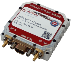
Power Amplifier for Datalink Range Communications


Figure 1: NuWaves NuPowertm Micro L & S Band Power Amplifier


If the application requires either increased range or data rates, the designer is left with two options. One is to improve the performance of the antenna through the use of exotic antenna designs. Unfortunately, many applications are limited to simpler omni-directional systems out of a need to meet operational requirements such as flight envelopes. The second option is to utilize an RF power amplifier. Amplifiers can provide increased data throughput and range, both with and without the use of specialized antennas. Augmenting the transceiver through the integration of an amplifier allows the designer to overcome the impact of such things as free space propagation path loss, insufficient antenna gain, and when paired with a LNA can result in increased receiver sensitivity. Every 6 dB increase in SNR results in the doubling of the effective range of datalink, meaning that an amplifier that can combine high power output, small size, and electrical efficiency can be an ideal solution for applications such as man or vehicle portable communications links and Un-Manned Aerial Systems.

NuWaves Engineering has developed a wide variety of off-the-shelf RF amplifiers with rich features to support mission-critical CONOPS in telemetry, ISR, and tactical communication systems applications to handle all of your datalink range needs. Frequency ranges are available from UHF through C-band with output power levels ranging from 5 to 100 WAll NuPowerTM PAs and NuPower XtenderTM BDAs are designed, built and tested in-house under NuWaves’ Quality Management System (QMS) certified to AS9100:2009 and ISO 9001-2008 standards, which ensures that each product arrives on-time and defect-free. Most models are in-stock, and are available for same-day shipment on orders placed before 2pm. NuWaves also boasts a full suite of state-of-the-art design and simulation tools, test and measurement equipment, prototyping equipment and a full-scale production facility to provide custom solutions to your specifications. Contact NuWaves today to extend the range of your communications systems and don’t forget to check out our RF Amplifiers and Frequency Converters. – by Ryan Foster Nu Waves Engineering

Mark Hoffman No Comments

Do You Need a Go-To Amplifier?

As a radio designer, it’s nice to have a go-to amplifier that you can use and reuse for a wide range of application frequencies, linearity requirements, bias voltages and currents. The GRF2013, part of Guerrilla RF’s standard DFN-6 portfolio, is a device that you can turn to over and over again for a wide variety of requirements.


Key Strengths of GRF2013:

  • Outstanding RF performance  over a wide range of bias conditions
  • Flexible biasing: Vdd can range over 2.7 to 5.0 volts with Iddq adjustable from 15 to 100 mA
  • Internally pre-matched to 50 ohms. A single set of external components yields multi-octave bandwidths from 50 MHz to 4 GHz and beyond
  • Automotive qualification coming soon
  • Part of GRF’s 1.5 mm DFN-6 portfolio, which offers over 20 devices using the same package, pin out, and layout

The GRF2013 data sheet focuses on 700 to 3800 MHz performance at 5.0 volts and 90 mA Iddq. However, this amplifier also excels below 1 GHz with a 3.0 volt power supply (see charts below). Notice the flat gain, NF and linearity over the measured 200 to 500 MHz band.

GRF2013 is in full production and is pin/layout compatible with more than 20 devices using our standard 1.5 x 1.5 mm DFN-6 plastic package. Evaluation boards and samples are available now.

Guerrilla RF is committed to providing the high performance RF solutions you need in the long term, and we will be pleased to provide the applications support you need to successfully implement any of our devices. –  by Guerrilla RF


Mark Hoffman No Comments

How to Decrease EMI and Increase Radio Range?

Electromagnetic interference (EMI) reduces radio range, drastically decreasing the functionality of Internet of Things products. There are some local and intermittent EMIs that are eventually get addressed, thanks to the Wi-Fi protocols that come complete with automatic retry features. However, the interference coming from external sources are continuous in nature and can drastically reduce the range of a device’s onboard radio. This kind of interference has to be addressed by the right mechanical and PCB design. But what about the interferences that come right from your own product?  Here are some useful tips that will help you minimize the EMI being emitted by your product and improve radio range:

PCB Shielding

Metal shields isolate circuits and prevent interference from reaching the antenna. At the same time, the antenna needs to be present outside the shield for receiving signals. So, shielding the interference sources is a better option than shielding the receiver. The Faraday cage is the best shielding solution available that provides a conductive box without any seams around the shielded circuitry.

However, you must develop metal shields with minimal contact resistance. And, there are several options to achieve this:

  • Pick clear chromate instead of aluminum as it provides decent conductivity while resisting corrosion.
  • Use an overlapping structure for an increased area and decreased contact resistance.
  • Minimize contact resistance through gaskets that rely on screws outside the gasket for more reliable contact and compression force.

Select the Right Clock Frequencies

Certain circuits are never switched off, and the resulting interference affects the receiver’s sensitivity. In a controller board, for example, clock oscillator signal harmonics cannot be controlled easily and lead to interference. There is one clock of 19.2 MHz and another of 25 MHz in a Raspberry Pi design. While the latter falls between the popular non-overlapping Wi-Fi frequencies, the former falls inside the Wi-Fi frequency channels. So, even though the 25 MHz clock doesn’t solve the interference issue entirely, it does help to a certain extent.

Check for EMI Issues

Detecting interference issues becomes easier with a spectrum analyzer. Select one that has greater maximum frequency than the system radio’s highest frequency. When an antenna probe is connected to this analyzer, it can detect design problems and locate interference sources. No wonder this setup is used by the FCC to test for EMI compliance and radio performance issues.

Switching up the components of a PCB can work wonders when it comes to decreasing EMI interference and improving radio range. Sure, it’s better if you detect all the problems as early as possible, but it’s worth noting that following the steps above can result in a design that minimizes EMI emission and prevents interference from affecting other parts of the radio system. To know more about EMI shielding, click here. -LeaderTech

Top